The Best Place for the Reverse Polarity Protection Diode Circuit Diagram each protection circuit are shown in Table 2. Use a circuit that is suitable for your application. V Table 2. Types of protection circuits and their advantage and disadvantage Reverse current prevention circuit TReverse current bypass circuit Circuit diagram DO IN UT C IN C T V IN V I E Figure 1 LDO IN OUT C IN C OUT V IN OUT I REVERSE Figure 2 This electronics video tutorial explains how to protect your circuits from reverse polarity damage using diodes.What Is a Diode? h

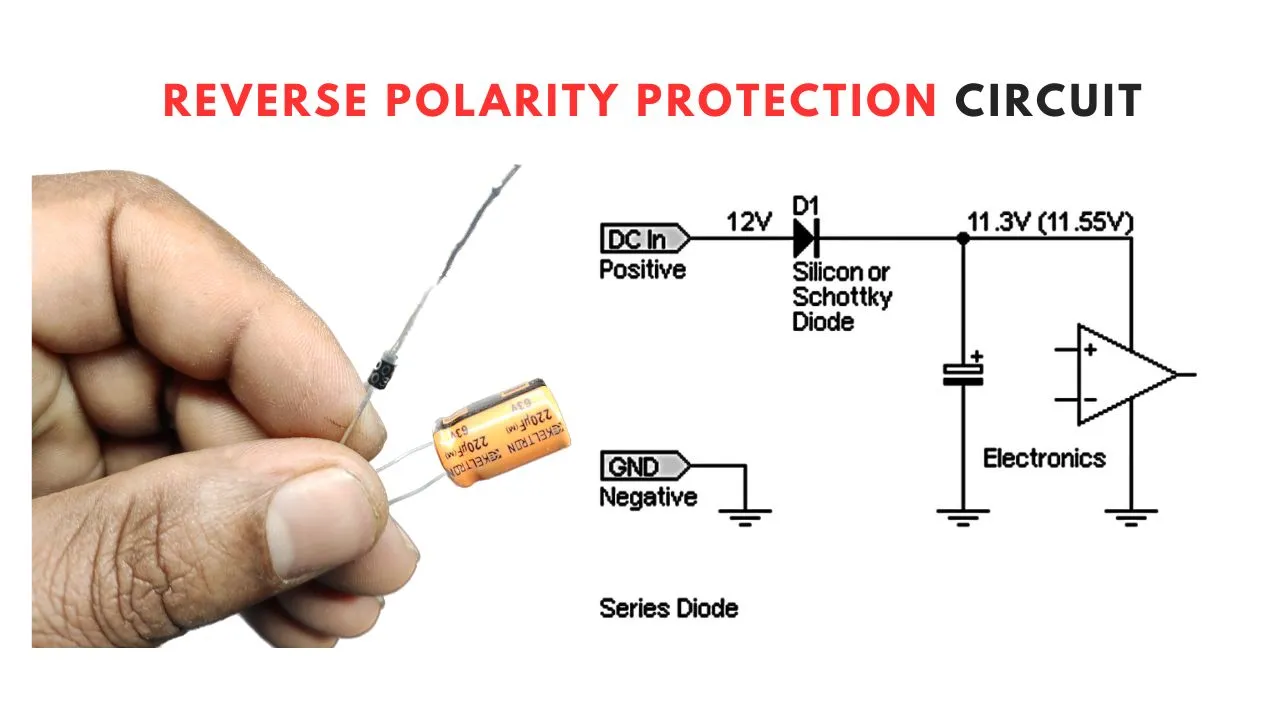
Reverse Polarity Protection with a Schottky Diode. An easy way to mitigate both of the above disadvantages is to use a Schottky diode instead of a normal diode. This approach reduces voltage loss and power dissipation. I'm not sure how low Schottky diodes can go, but in some cases the forward voltage can be below 300 mV.

Reverse Polarity Circuit Protection Using Diodes Circuit Diagram
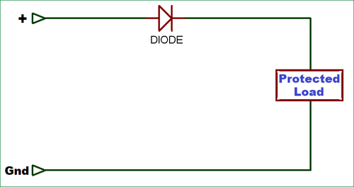
A variety of circuits can provide this assurance. Diodes Provide the Simplest Protection. The simplest form of battery-reversal protection is a diode in series with the positive supply line (Figure 1a). The diode allows current from a correctly installed battery to flow to the load and blocks current flow to a backward-installed battery. The circuit below shows the improved design of using a protection diode in a circuit. To protect a component in a circuit, a diode is normally placed reverse biased in parallel with the component. When a diode is placed in parallel with the component you want protected reverse biasd, if current flows through the circuit in reverse, the current
Another diode-based protection method is to wire a diode in parallel to your main circuit, causing it to block current when voltage is applied correctly. Instead, the voltage travels through the main load. Once reversed, this diode provides an alternate path for electrons, largely bypassing the main circuit and protecting it from these effects. Defending Against Reverse Current: The Workings of Reverse Protection Diodes Lgesemi: This guide offers a thorough examination of the vital role reverse protection diodes play in shielding electronic circuits from reverse current flow damage.It looks at how these diodes operate, how they're used in different systems, and what technological trends are influencing their advancement.
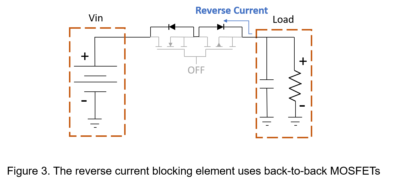
Reverse-Current Circuitry Protection Circuit Diagram
This circuit appears to be a simple power supply circuit with a protection diode and an LED indicator. The diode ensures current flows in only one direction, protecting the circuit from reverse polarity damage. A rocker switch is used to control the power to the LED, which likely serves as an indicator for when the power is on.