How does the photodiode help maintain the output from this laser Circuit Diagram In most applications, the photodiode operates in photoconductive mode with a reverse bias (Figure 2). Figure 2: The reverse biased photodiode produces a current proportional to light intensity due to the creation of electron-hole pairs in the depletion region. The blue-filled circles represent electrons and the white circles signify the holes. Photodiodes are one of the popular components used to sense incident light in electronic circuits. It has wide range of applications like Remote control, alarms, sensory applications and so on. This article explains What is a Photodiode, How it works and how to use them in a circuit. Working of Photodiode : Some examples of specific applications of photodiodes are: Alarm circuit using photodiode: A photodiode can be used to detect an intrusion by breaking a beam of light that falls on it from a light source. When there is no obstruction in front of the photodiode, a reverse current flow through it due to the incident light.

Applications of Photodiode. Photodiodes are used in many simple day to day applications. The reason for their use is the linear response of photodiode to a light illumination. When more amount of light falls on the sensor, it produces high amount of current. The increase in current will be displayed on a galvanometer connected to the circuit.
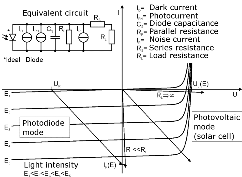
I Characteristics, Applications Circuit Diagram
There are two types shown in Figure 1. The first is the better known photovoltaic diode (solar cell), which produces current when light shines on it. The second is the photoconductor, which is a reverse-biased photodiode. Light shining on the photodiode causes its resistance to the reverse bias current to decrease.

The following two applications circuits show how a foolproof implementation can be done using photodiodes through 30 kHz carrier modulation frequency. These are selective preamplifier based photodiode alarm circuits, and will respond to a specific band of frequency, ensuring a foolproof operation of the system.

How Photodiodes Work and Their Applications Circuit Diagram
The project about light sensor circuit shows the application of photodiode to detect the presence of light. This light sensor can be used as an intermediate circuit [[wysiwyg_imageupload::]]in various applications to detect the presence or absence of light. The sensitivity of the sensor can be adjusted using the preset. This circuit is based around a LM339 comparator along with variable